Overview
I machined this phone stand as part of my machine shop course. Below is an overview of its creation.
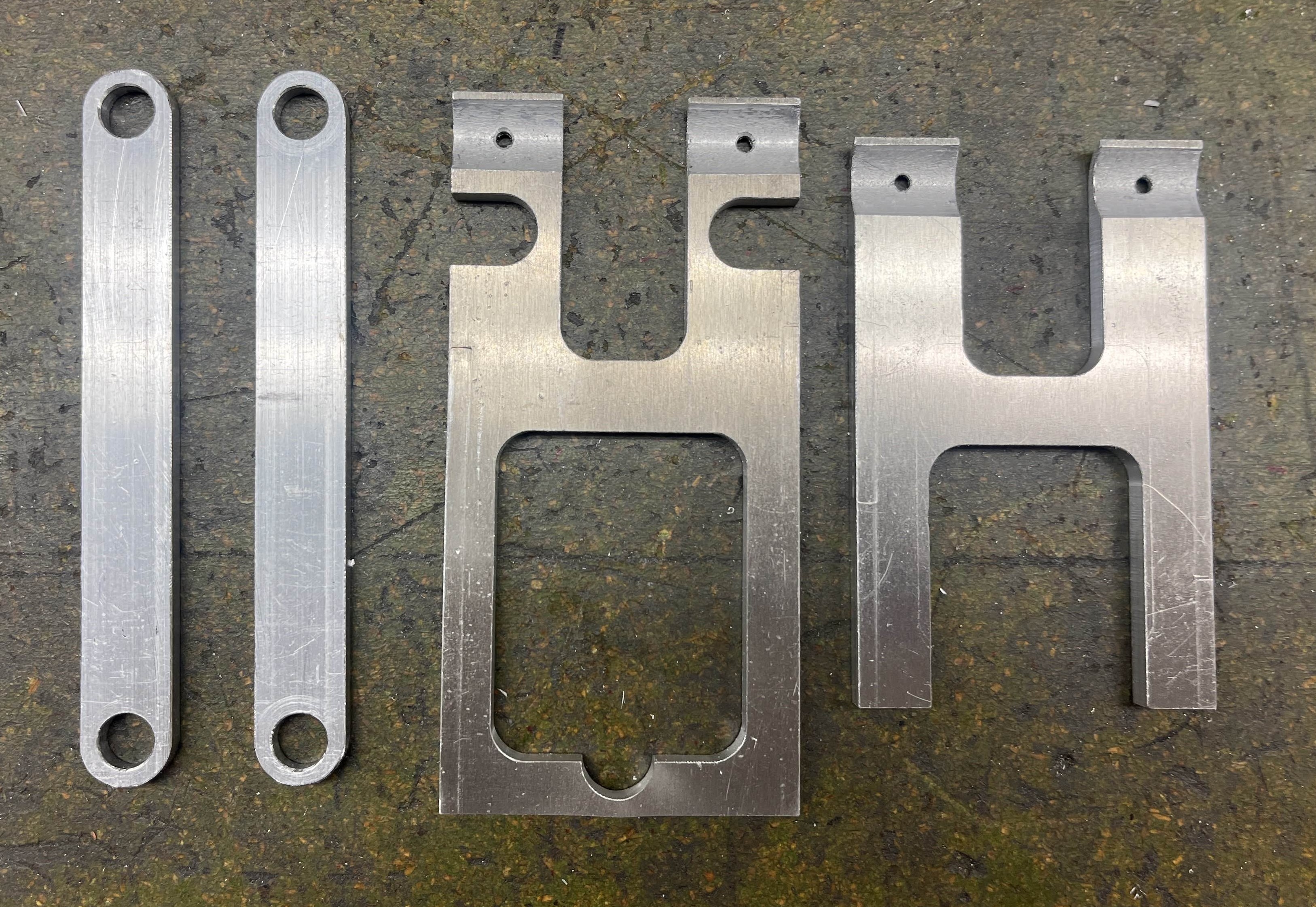
Large Aluminum Components
The centre and right parts were first cut oversized with the water-jet cutter, then all dimensions were brought within tolerance on the mill. The circular groove was cut with a ball-nose endmill and fillets were added with an external radius endmill (fillets are on the backside, matching the contour of the circular groove; difficult to see in this photo). The rounds on the two left parts were also added using an external radius endmill, and holes were drilled in all parts.
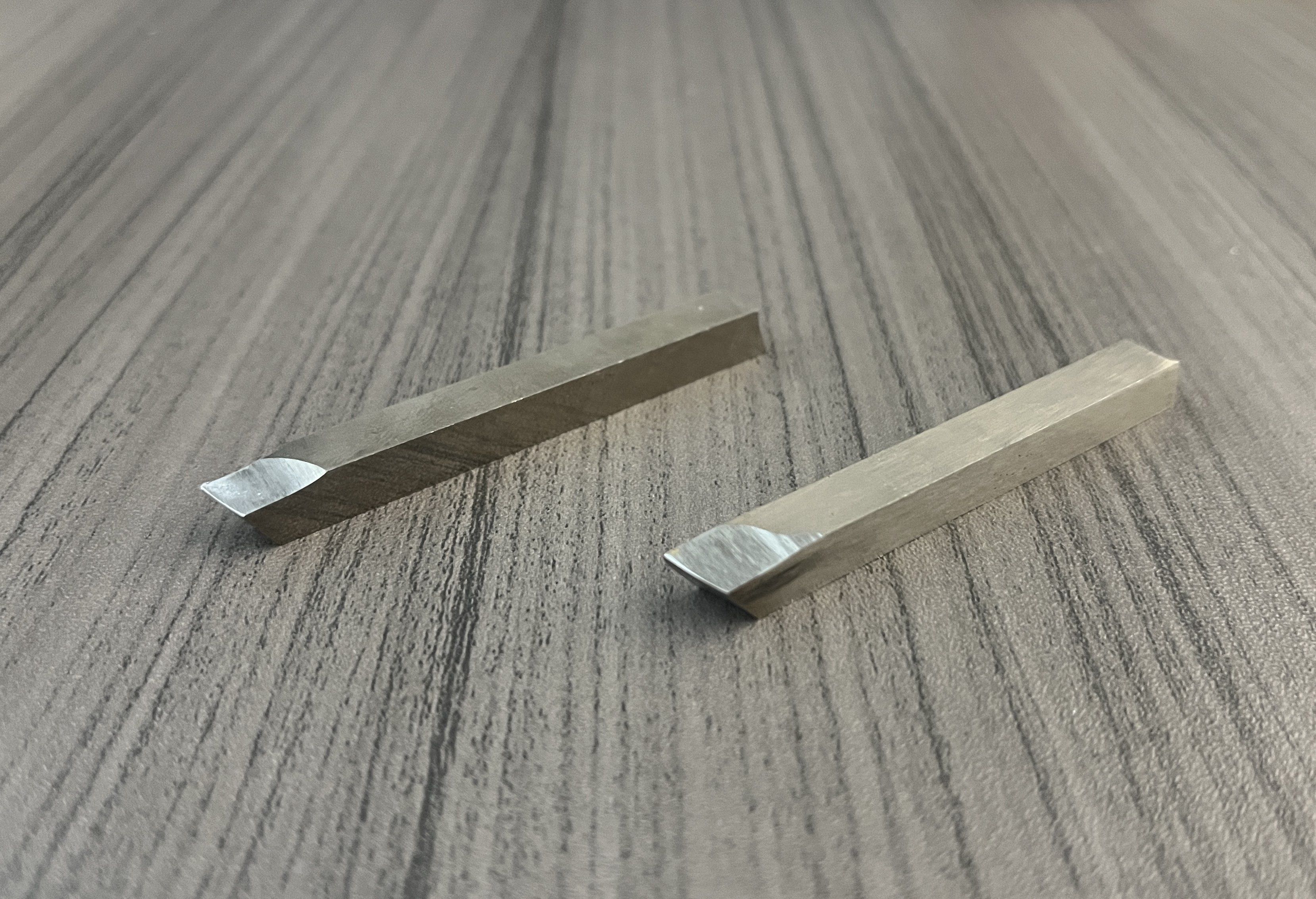
Lathe Tooling
Before working on the lathes, I first had to make cutting tools for them. I made the following two tools out of cobalt steel blanks. On the left is a tool designed for long-chipping metals, such as aluminum and steel. It has an extra facet to help with chip evacuation. On the right is a tool designed for short-chipping metals such as brass. I ground these tools on the bench grinder.
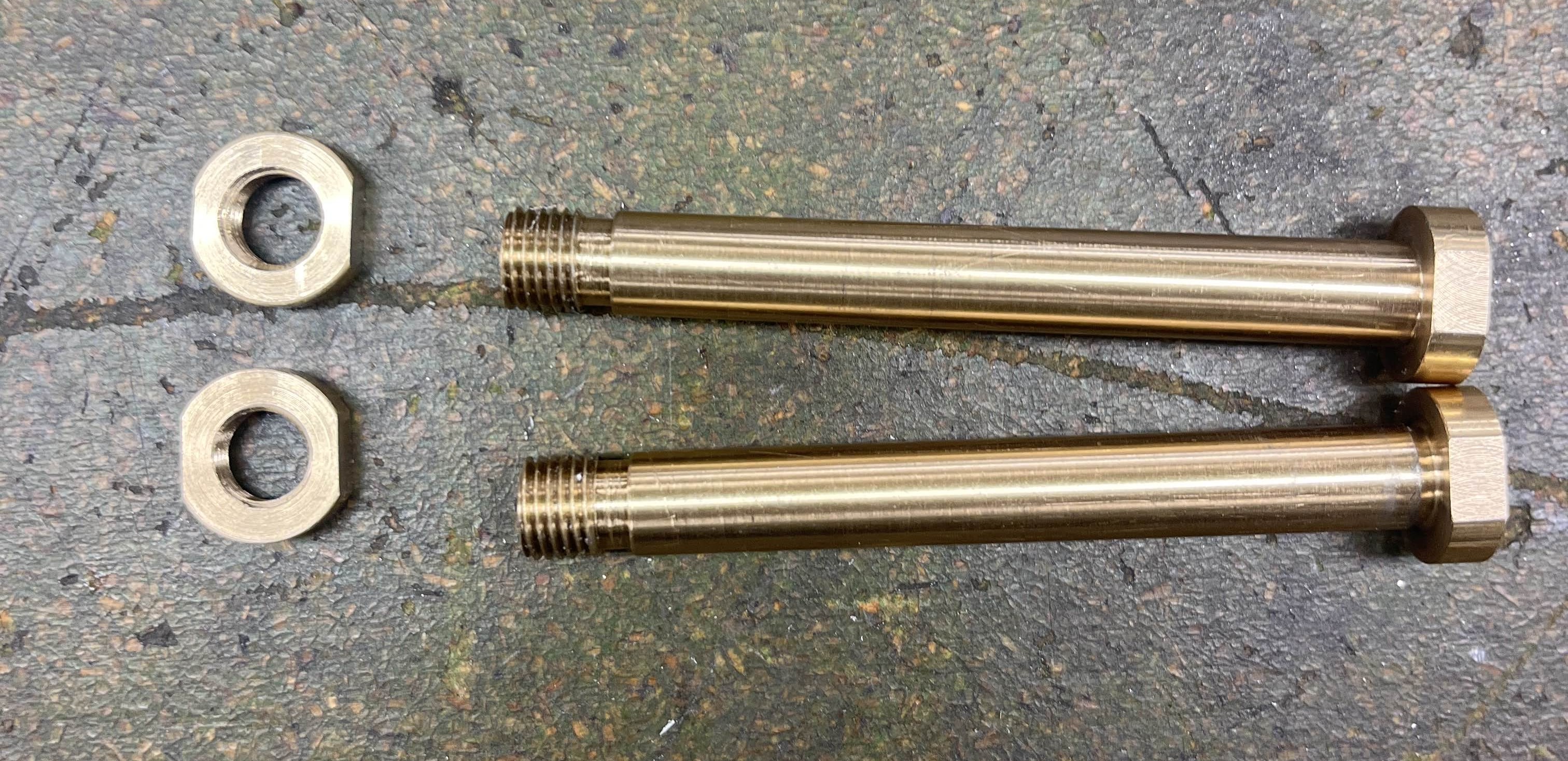
Brass Shafts and Nuts
Below are the brass shafts that act as the pivots of the phone stand, and the nuts that hold it together. Both parts were first made on the lathe, then wrench flats were added with the mill.
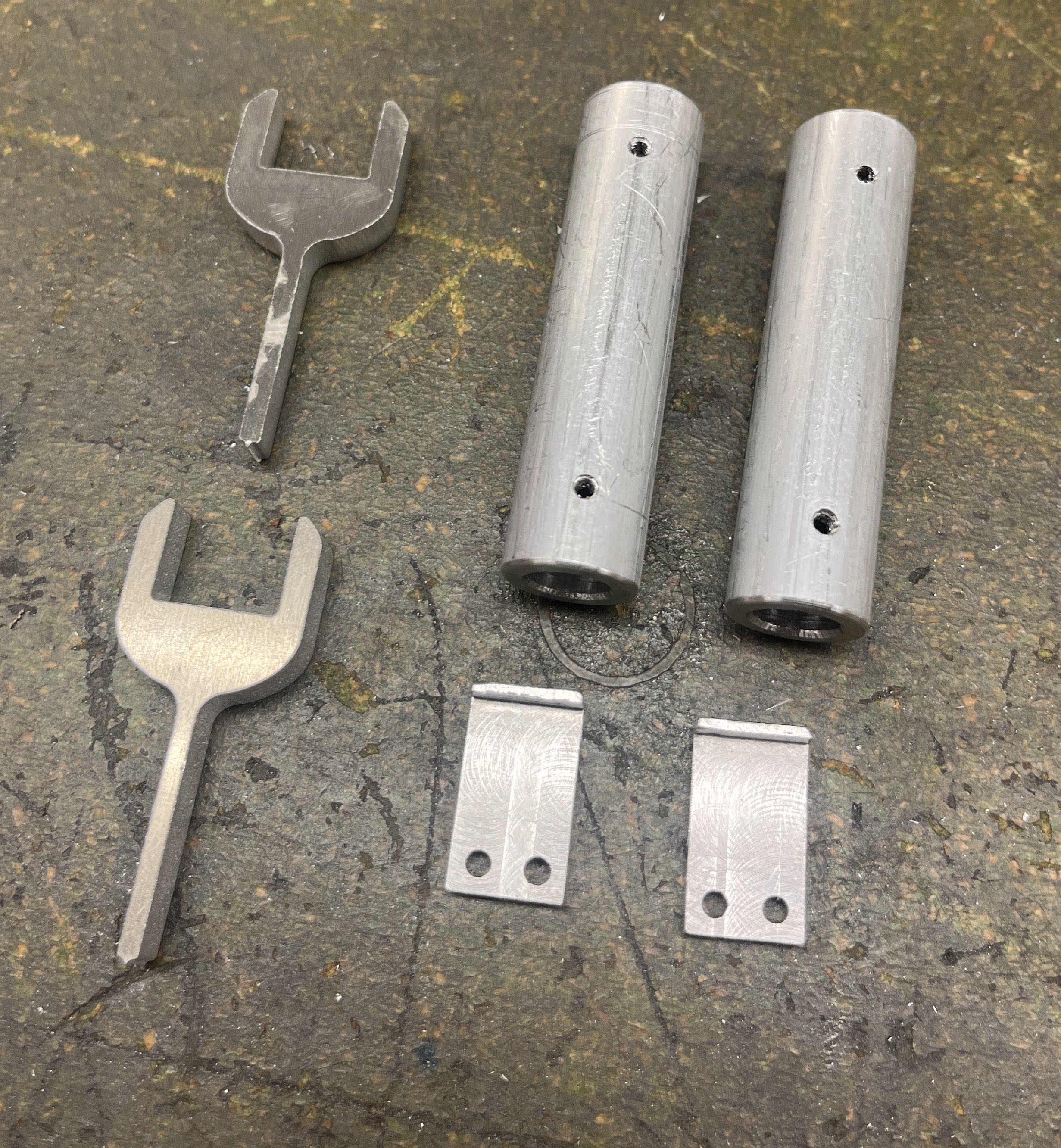
Remaining Aluminum Parts
The roundbar was bored out on the lathe, then the two small holes were drilled and tapped. The small hooks were made on the mill with a fairly straightforward procedure. The two wrenches were water-jet cut at the same time as the larger parts above.
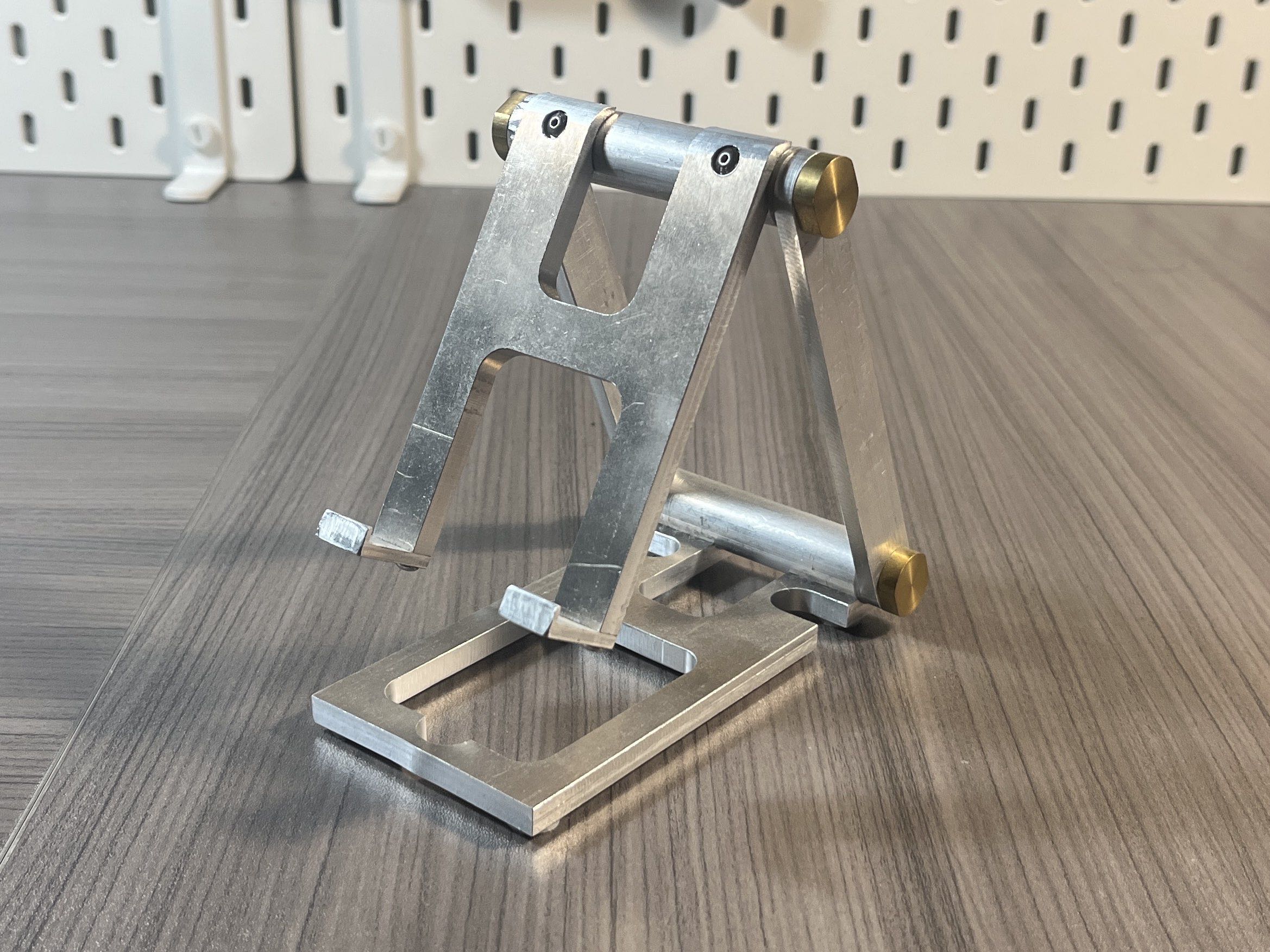
Final Assembly
Once all parts were machined, it was a simple assembly procedure. Nylon washers were placed on the brass shaft, to avoid metal-on-metal contact, and so the friction of the joints could be easily adjusted with the brass nuts.