Overview
The Problem: I have several USB-powered LED lights for my bedroom, which I never used for two reasons. 1) It’s inconvenient to need to plug in USB cables to turn the lights on. It’s an eyesore to have extra cables lying around, but if I hide them (such as with a power bar under my desk), they’re difficult to reach. 2) I often don’t have USB ports available for extra lights.
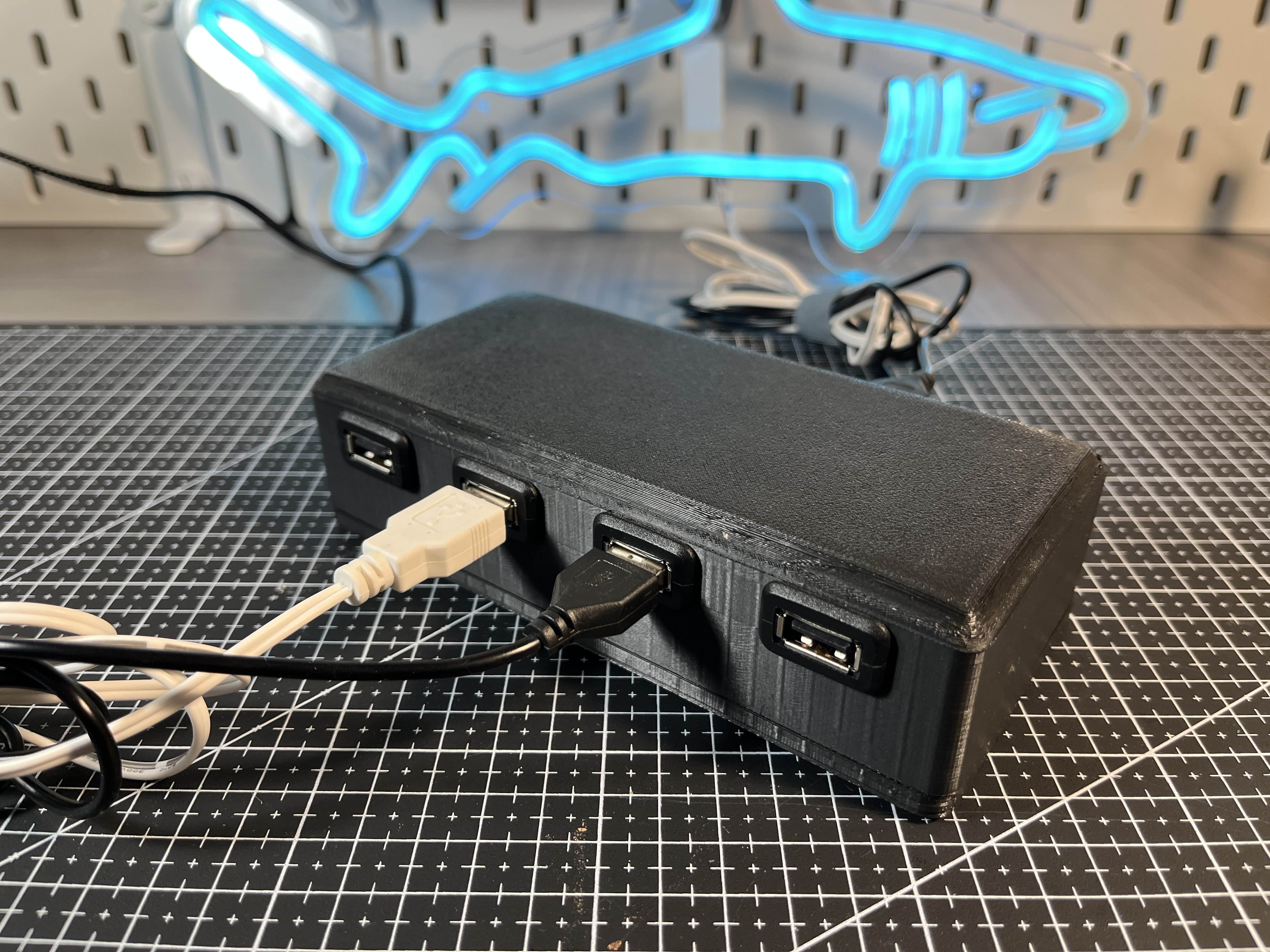
The Solution: I created a smart USB hub that can control several LED lights via a Google Home, requiring just a single USB port for power.
System Architecture
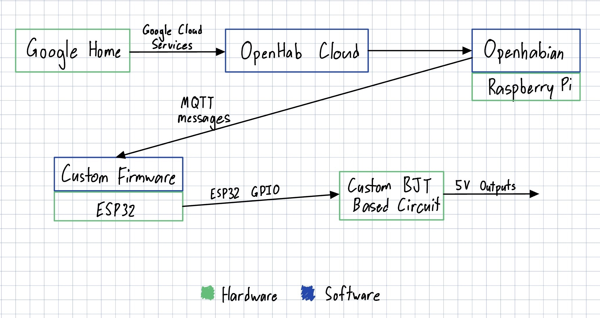
The system consists of a Google Home, Raspberry Pi, and ESP32, connected to a BJT-based circuit to power USB ports.
The system flow is:
→ Google Assistant command
→ cloud bridge
→ home automation server on Raspberry Pi
→ MQTT message
→ ESP32 firmware
→ transistor switching stage
→ 5V USB outputs for LED lights
BJT Circuit and USB Outputs
The ESP32 GPIO pins cannot drive the USB loads directly, so each port is controlled through a transistor switching stage. This stage acts like an electronic switch that turns a port on or off based on a signal from the ESP32.
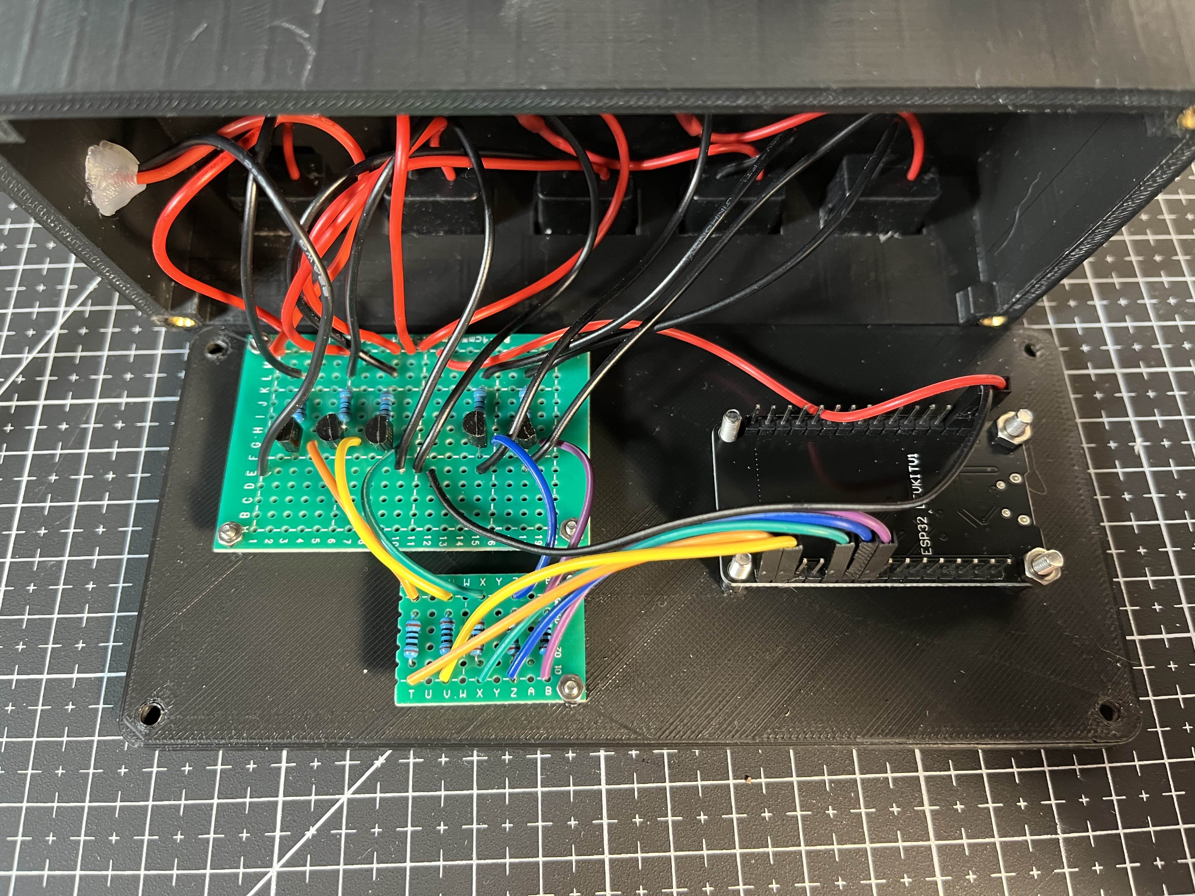
I designed and soldered a custom transistor-based board for this. I chose to use the 2N2222 BJT for this, as it was easy to source, inexpensive, and met all my electrical requirements. Below is a schematic I made in KiCad, and a picture of the circuit. I included the 10 ohm resistors to limit the collector current. This will dissipate power, and the lights won’t receive the full 5 volts; however, since I didn’t have any information on the current draw of the lights, I decided it was worth it to protect the BJTs. I haven’t noticed any issues with having the resistor in the current path.
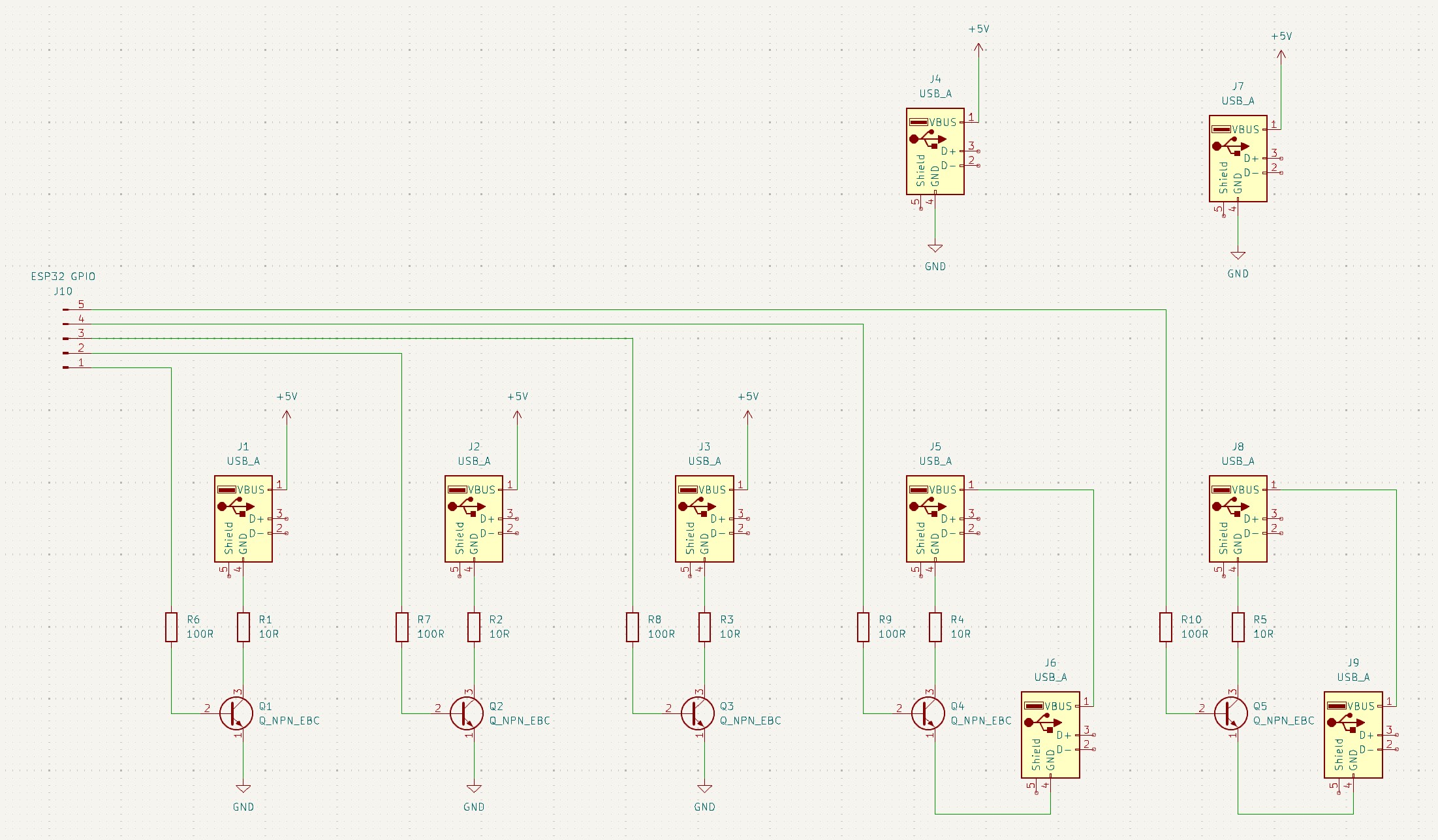
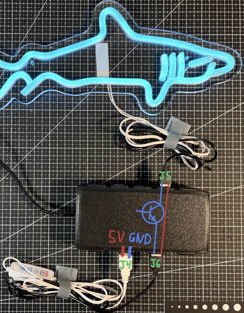
There are two “types” of USB ports in the hub. The first three are simple on/off ports; they have an NPN transistor on the low side of the load, allowing them to be turned on or off. The remaining ports are for lights with an in-line controller. When these lights are plugged in, they do not turn on automatically, you need to press a button on the controller or remote. To make them controllable by my Google Home, I decided to have the controller always powered, with the BJT switching circuit between the controller and the light. I once again used an NPN transistor on the low side of the load. Below is a visualization of how this “passthrough” circuit works.
Software and Integration
Raspberry Pi Home Automation Server
A Raspberry Pi acts as the local server for automation logic. It runs openHABian, a Linux OS optimized for home automation. It receives commands from a cloud bridge, and sends commands to the ESP32.
MQTT Messages
The Raspberry Pi communicates to the ESP32, using the MQTT protocol. The Pi runs an MQTT broker, which hosts ‘topics’ that devices can publish and subscribe to. There is a topic for each light, which the Pi publishes on/off commands to. The ESP32 is subscribed to those topics, so it can see when a new command has been published to a topic.
ESP32 Firmware
I wrote a fairly simple firmware for the ESP32. During setup, it connects to my local network and the MQTT broker. I also added code to reconnect to these automatically if the connection is ever lost. The ESP will then continuously listen to the MQTT topics. When the ESP detects a new message, it will initiate a digitalWrite to the pin associated with the correct USB port.
Google Assistant Cloud Bridge
To connect Google Assistant to my local server, I integrated a cloud-based bridge, openHAB Cloud, that forwards voice commands into my home automation system. OpenHAB Cloud integrates nicely into the Google Assistant ecosystem, as well as my local home automation server.
Enclosure Design
I designed an enclosure in SolidWorks and 3D printed it to house all the components. It’s made from two parts, fastened together with heat-set inserts and M4 bolts. I added standoffs for the ESP32 and BJT board, which are held in place with additional hardware.

Results
The finished hub successfully controls 5V LED lights through Google Assistant voice commands. Once it was configured, it behaved like a normal smart home device, except the hardware and control path were fully custom. The system has proven to be exceptionally robust. After resolving some initial sleep issues, I’ve never needed to debug or fix the system. There are no issues with unplugging any of the components, such as the USB hub, the Pi server, or my local network. Once they’re all powered back on, the system will reconnect automatically.