Overview
I built a closed-loop controller that sets and actively regulates the RPM of a DC motor using feedback from an optical sensor. The motor’s speed is measured as a pulse count. That count is latched and converted into an analog voltage, and an op-amp circuit controls a power transistor via proportional-integral control to correct the error.
Throughout this lab course, I kept a detailed lab notebook. I documented my progress, challenges, and troubleshooting procedures.
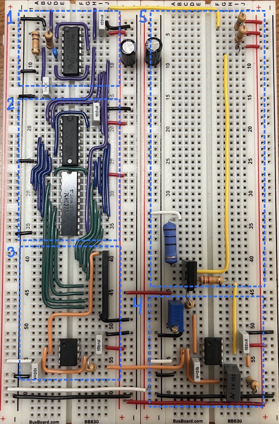
System Architecture
The full loop has five main blocks:
- LATCH and RESET signal generation
- Counter and D-latch (stores the measured speed)
- 8-bit DAC (converts the stored count to an analog feedback voltage)
- Error signal amplifier (P.I. control)
- Motor sensor and motor driver (phototransistor sensing + BJT power stage)
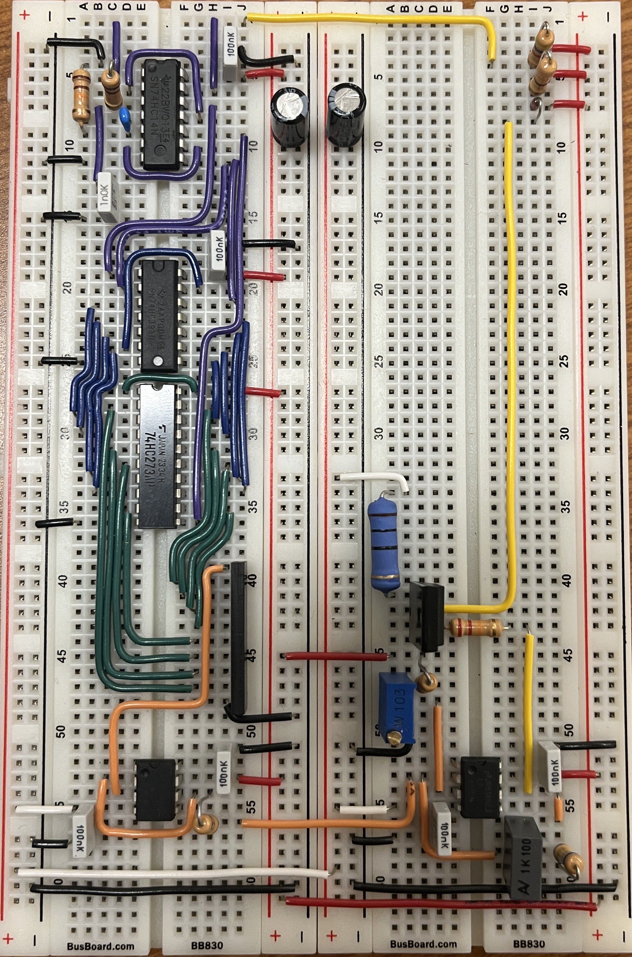
Circuit Breakdown
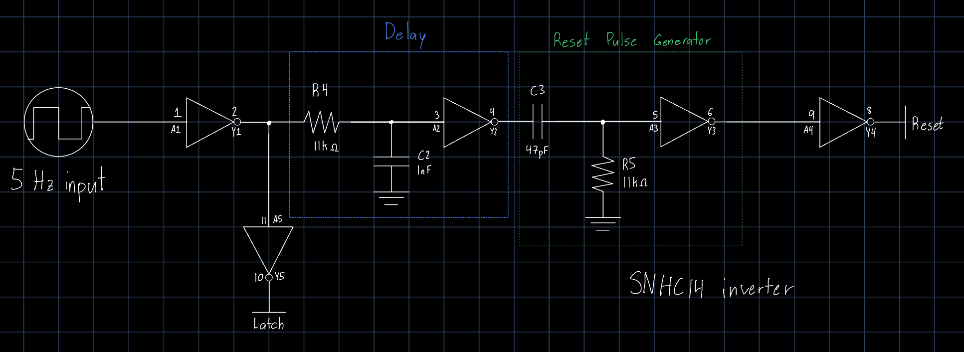
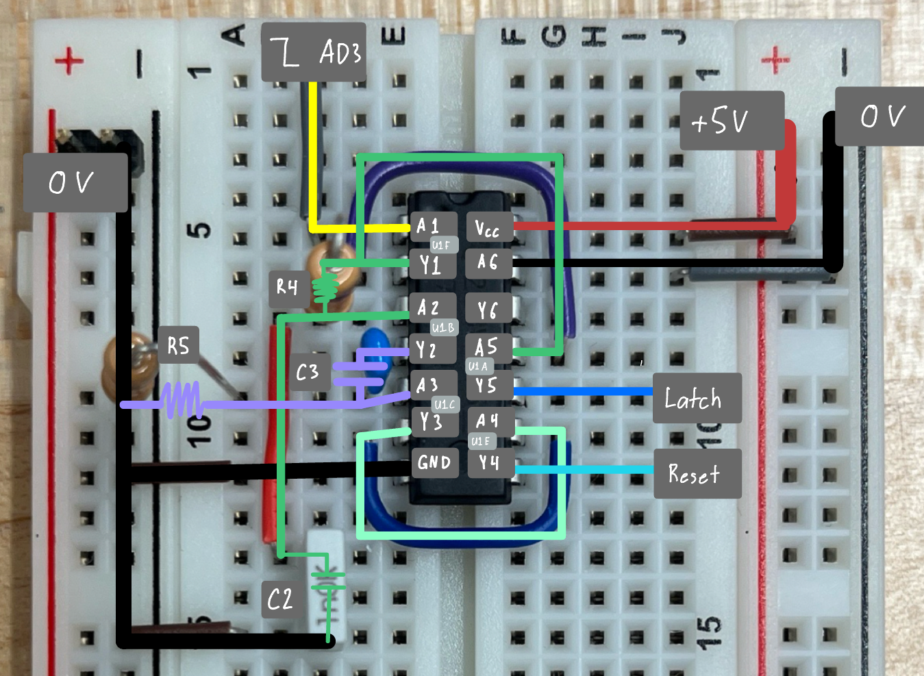
1) LATCH and RESET generator
This section creates two timing signals used for measuring the motor speed. The signals go to the counter and D-latch in section 2).
A 5 Hz square wave is used as a timing reference. The LATCH signal is a square wave that’s sent to the D-latch. After a short delay, a RESET pulse is sent to the counter.
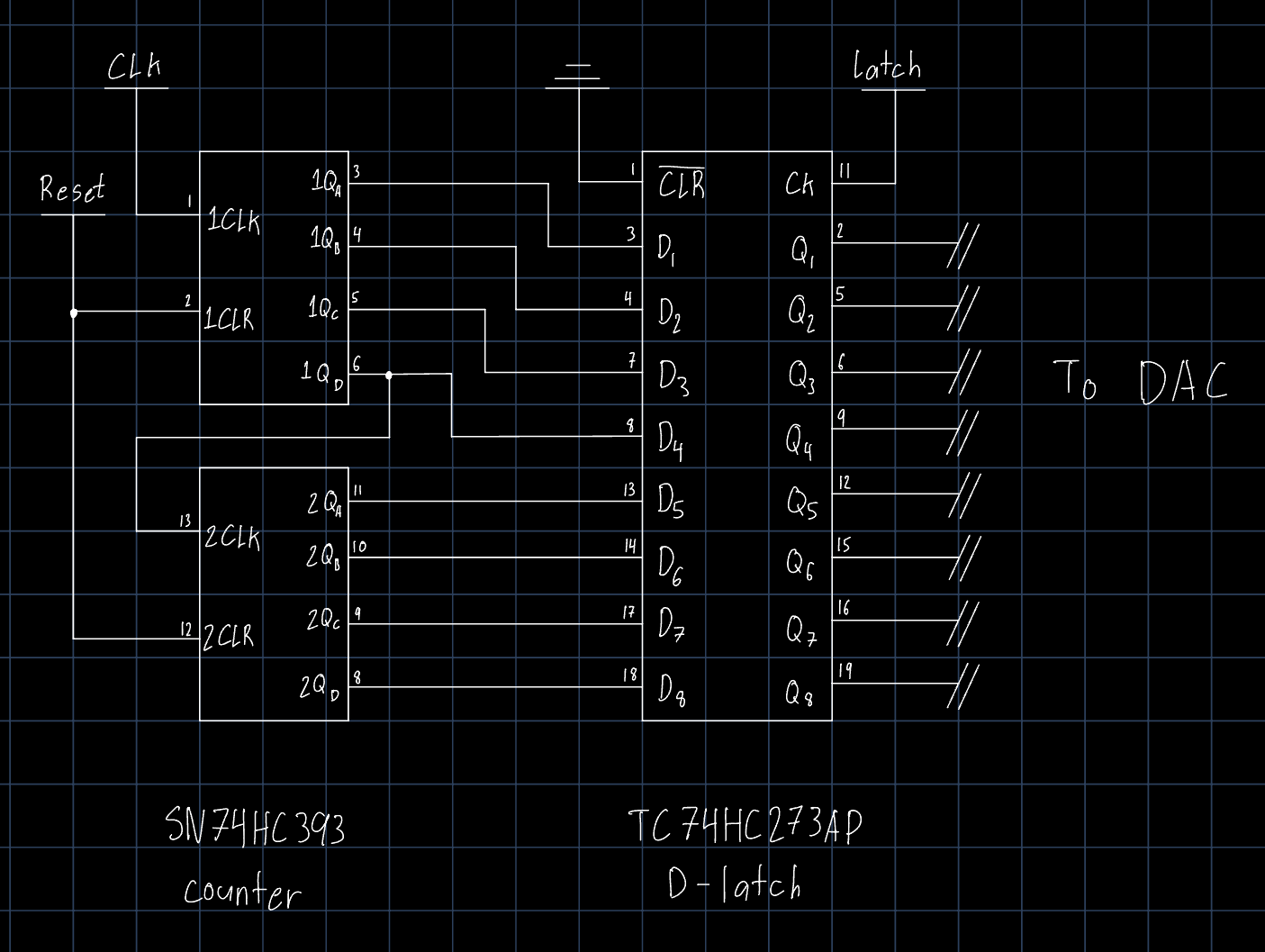
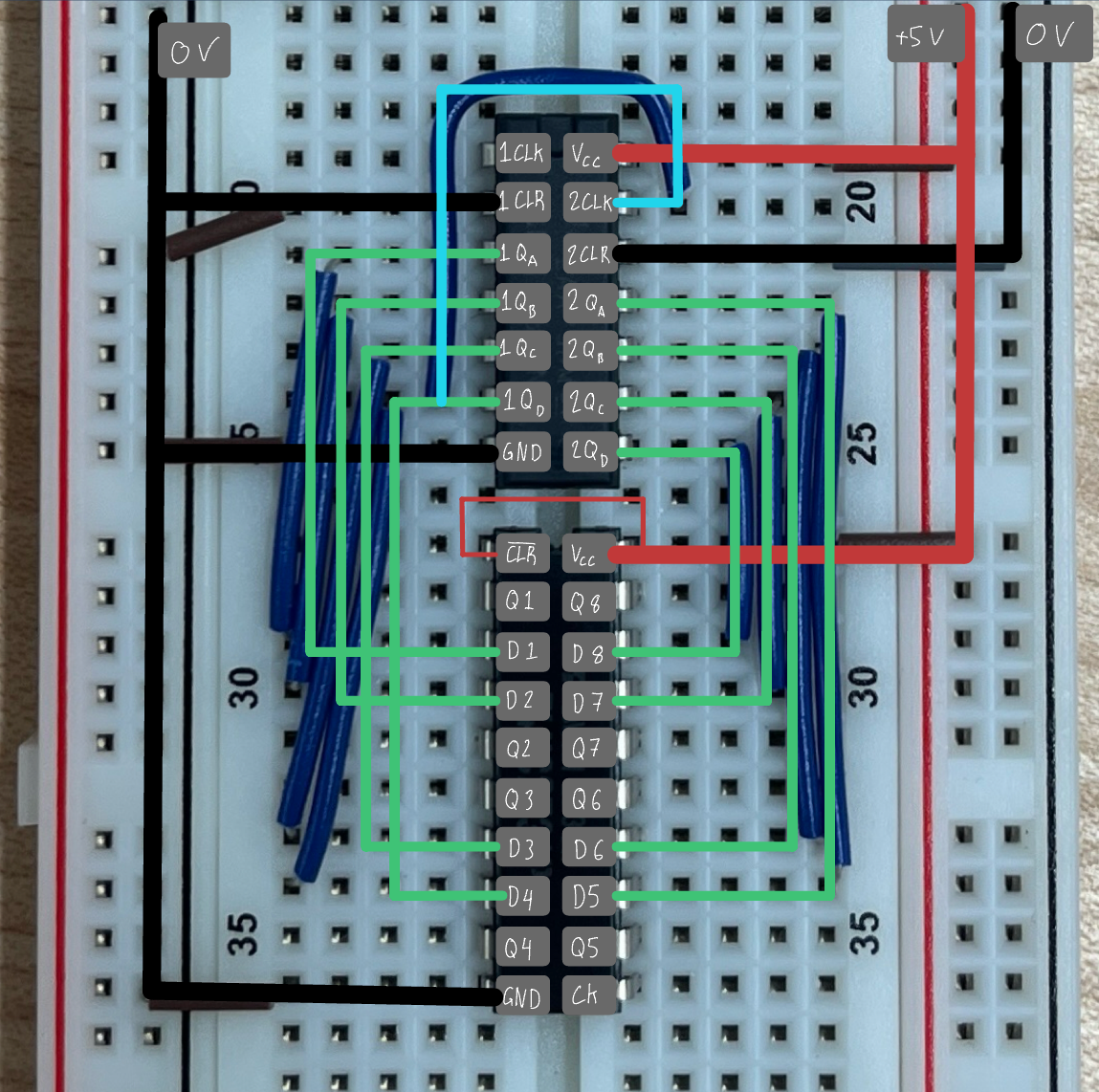
2) Counter and D-latch
The counter measures speed by counting clock pulses produced by the motor sensor during each measurement window. This count is stored digitally, as an 8-bit number. When the LATCH signal from section 1) is sent to the D-latch, it stores the current value in the counter. When the RESET pulse is sent to the counter, it’s reset, and begins counting anew. The delay between the LATCH and RESET signals is critical, as it allows the count to be latched before it’s reset.
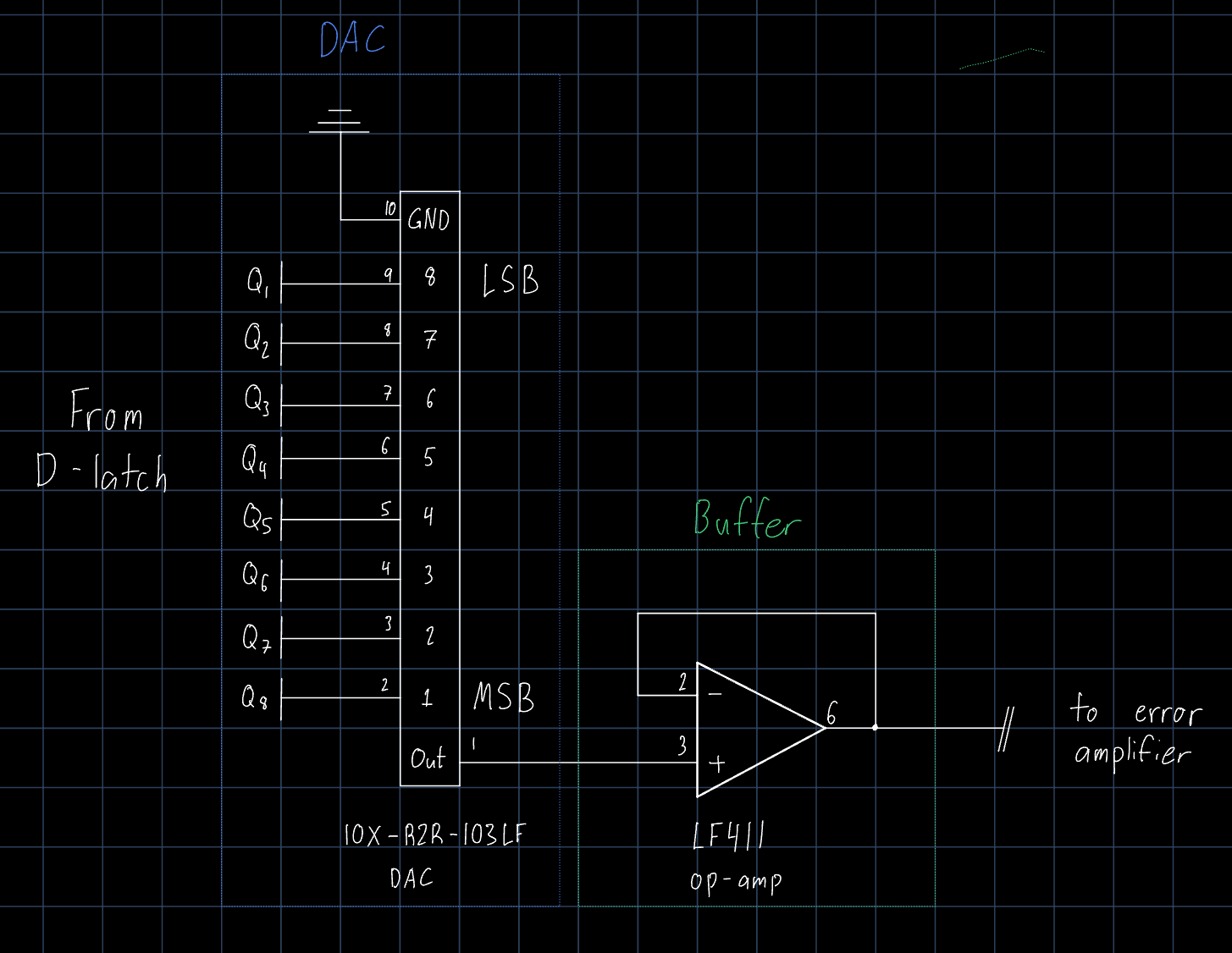
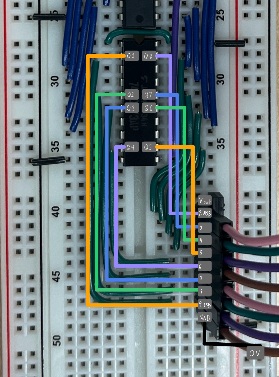
3) 8-bit DAC
The latched 8-bit value from section 2) is converted into an analog voltage using an R-2R ladder network. The analog signal represents the measured speed in a way that can be compared with a user-defined set-point voltage.
A buffer op-amp is used after the DAC so its output is not loaded by the following section.
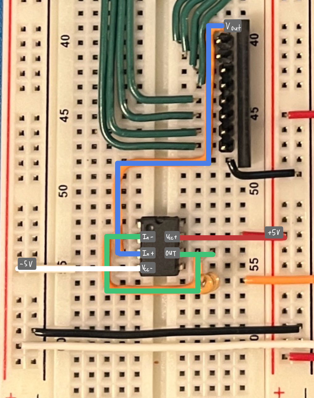
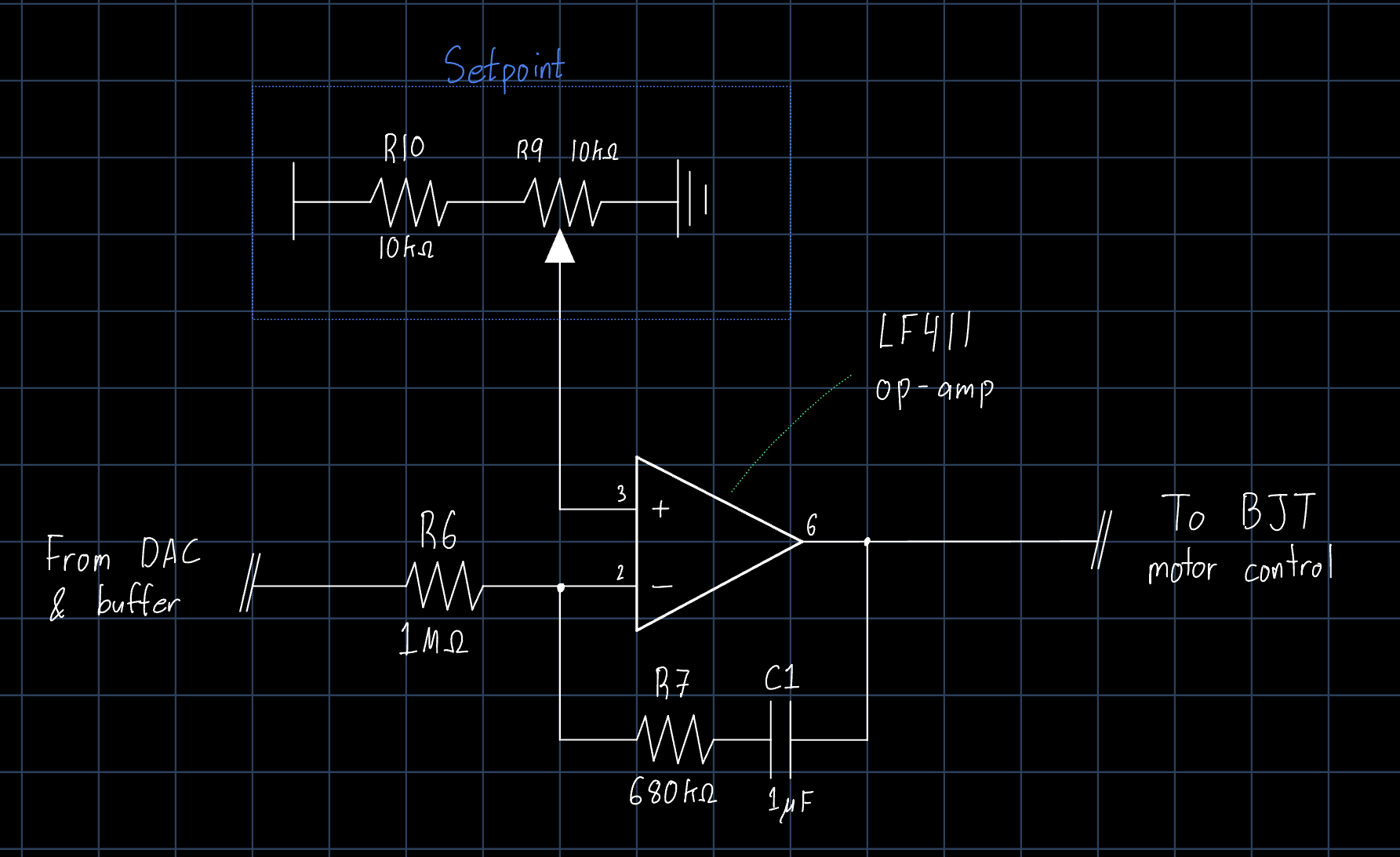
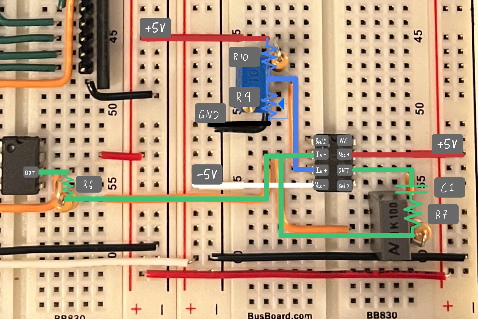
4) Error signal amplifier (P.I. control)
This section compares the output voltage from the DAC to a set-point voltage controlled by a potentiometer. This op-amp circuit provides both proportional and integral control.
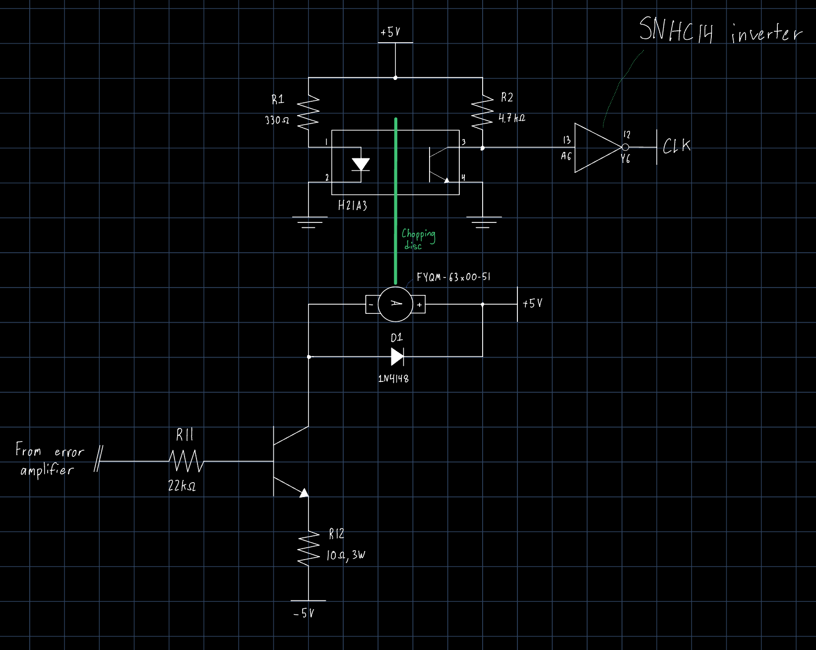
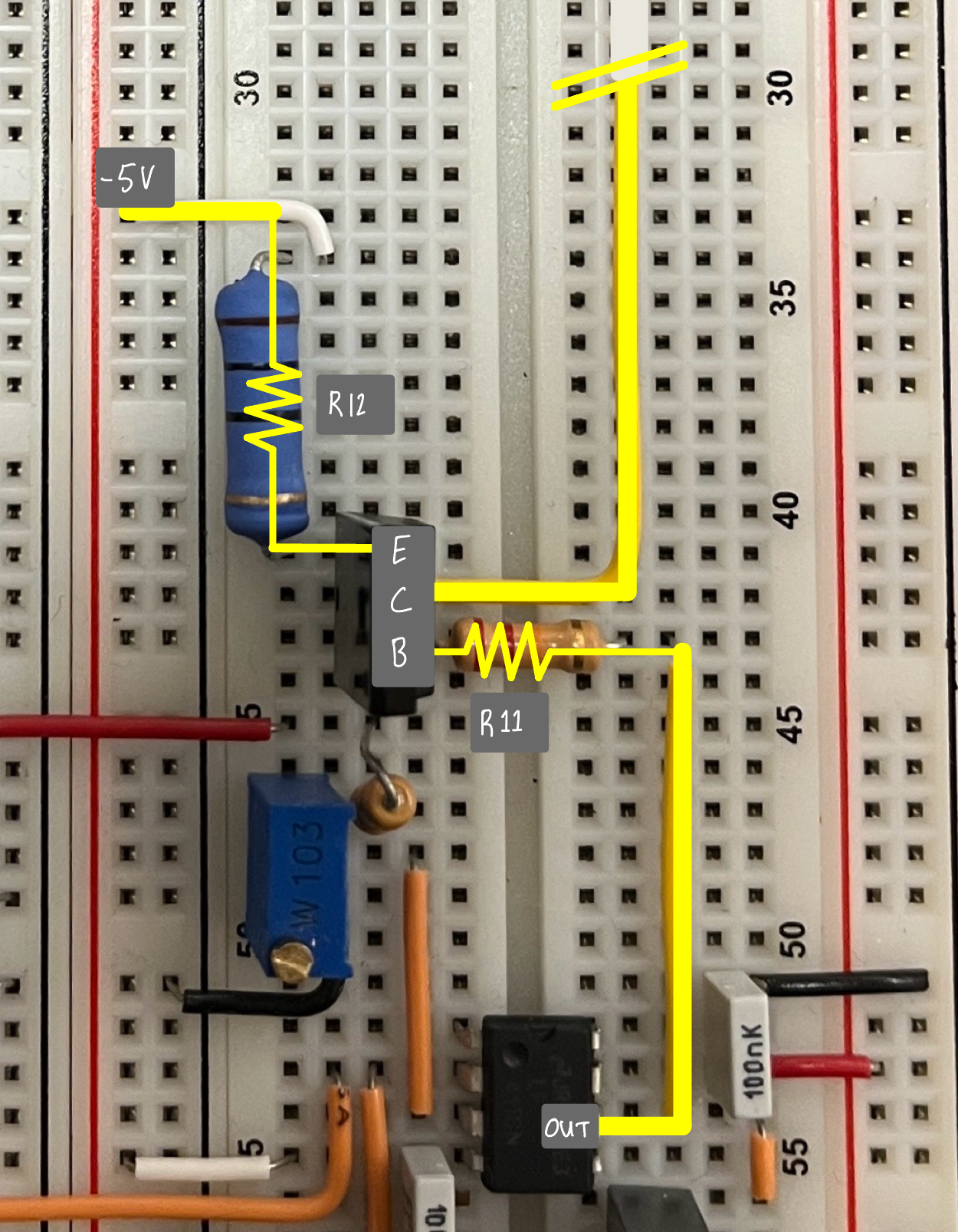
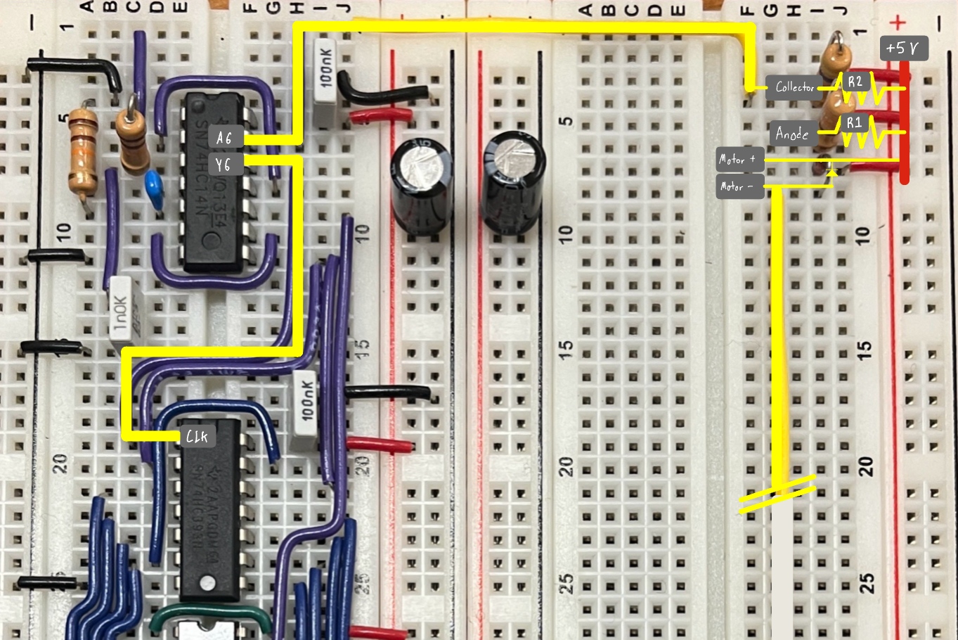
5) Motor sensor and motor driver
The driver stage uses a BJT to control the current sent to the motor based on the output of the previous section. A flyback diode protects the circuit from the inductive nature of the motor.
Attached to the motor is a slotted disc, so that its rotation can be measured with an LED and phototransistor. This produces a pulse train which is input to the counter in section 2). The disc I used had 10 slots, meaning there are 10 pulses per revolution.
After assembling the circuit, I proved its functionality, such as the adjustable speed set-point and integral control, to the course staff.